
1. ElectroBraid Commitment to Safety
The ElectroBraid system is designed to minimize horse injuries. Equally important, you must provide correct installation and proper maintenance.
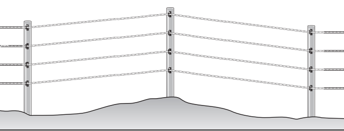
A collision with a rigid fence is the most frequent cause of serious horse injury. ElectroBraid is not rigid – it is resilient, like a boxing ring. When a horse at full gallop impacts ElectroBraid , it usually bounces right back with no damage to horse or fence.
ElectroBraid is a psychological barrier. Always maintain at least 5,000 volts and a good grounding system to ensure your horse will receive a significant electric shock – not just a "bee-sting". The shock from a UL or CSA-approved energizer won't harm your horse because the shock is very low amperage for a tiny fraction of a second, but your horse will always respect ElectroBraid in the future.
Injuries with ElectroBraid are very rare. If an incident occurs, please call 1-855-EBFENCE so we can discuss the circumstances with you. Hopefully, we can take corrective action together to prevent any future injury.
2. Steps for Successful Electric Fencing
1) The Right Energizer for the Job.
There are a variety of energizers on the market, but we only recommend low-impedance energizers, certified safe by UL or CSA and with at least 2 joules of output power. They put out a very short, low amperage pulse of electricity, which will not harm an animal or child. NEVER use "Weed Burners", "Weed Choppers" or continuous current fencers - these energizers have been banned in many areas as a fire and safety hazard and will damage ElectroBraid.
2) Install a Good Ground System.
Poor or improper grounding causes 95% of all electric fencing problems. You can have the most powerful energizer in the world but if the ground return is poor, your fence will not perform. Use a minimum of three copper-clad ground rods spaced at least 10 feet apart. Use the "hot-cold" technique by wiring the next-to-the-top strand as a ground line. Electrify all other strands. You may need more ground rods if you have dry or sandy soil.
3) Use Recommended Materials.
Do not use make-shift insulators or ordinary electrical wire. Building a system that uses copper-clad ground rods, brass-coated copper split bolt connectors, and copper lead-out wire will provide optimum electrical conductivity, reduce maintenance and increase the life of your fence. Staying with an all-copper system will prevent a type of corrosion called electrolysis, where dissimilar metals corrode when in contact.
4) Check your Fence Regularly.
Don't wait for something to go wrong. Check the voltage on your fence regularly using a reliable fence voltmeter. Track down and correct any electrical shorts. Eliminate the weed growth under the braid. Check the tension on the braid regularly to ensure each strand is tight. Posts can move due to frost heave or impact, so re-set the post and re-tighten each strand.
3. Planning your Fence
The installation of any fencing system begins before the first post is driven. The secret to getting the best value for your dollar is to plan thoroughly before you start construction.
Check Local Laws and Ordinances: Laws governing fences and electric fencing vary from county to county. Find answers to questions such as "How far must a fence be from a roadway?" "Can an electric fence be used in a suburban area?" and "Are warning signs required?" Check with your County Extension Office or your City Clerk's office.
Sketch Your Map:
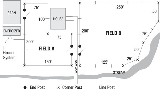
Begin by drawing a map of your property, including all significant features: buildings, roads, fields, swamps, woods, gullies, streams, and other features. Be sure to include power, telephone, gas, and oil lines, as well as underground cables.
- Mark the location of each end and corner post.
- Mark the location of each line post based on the separation you wish to use
- Mark the location of the energizer close to an electrical outlet
- Calculate the total length of your fence
- Choose the number of strands of braid you wish to use. We recommend 4 strands.
- Choose the type of line post you wish to use (wood, vinyl, or T-posts)
4. Calculating Your Needs
Online Fence Calculator:
Using the principles detailed below, you can help generate an accurate materials list using our online fence calculator at
It can make use of satellite images and help you determine accurate dimensions of your fence site perimeter.
Manual Calculation Process:
Multiply the length of your fence by the number of strands you wish to use and divide by 1000 feet =
_____.
This is the number of reels you'll need.
ElectroBraid Roller Insulators for End Posts, Corner Posts, Dips and Rises:
- Add the number of corner posts and the number of end posts and multiply by the number of strands = _____.
- Count the number of Line posts with vertical changes in direction (hills, gullies, etc.) and multiply by the number of strands = _____.
- Add these two numbers together (____ + _____) = _____. This is the number of ElectroBraid Roller Insulators you require.
Line Post Insulators for Brace Posts at Ends and Corners:
- Multiply the number of end posts by the number of strands = _______.
- Multiply the number of Corner posts by the number of strands and multiply by two = ______.
- Add these two numbers together = _______. This is the number of Line Post Insulators you will require for Brace Posts.
Line Post Insulators for Line Posts:
- Count the number of line posts and multiply by the number of strands = ______. This is the number of Line Post Insulators you will need for Line Posts.
- Depending on the type of line posts you plan to use, these may be the same or a different insulator from the Line Post Insulator you plan to order for your Brace Posts (see above).
Insulated Copper Lead-Out Wire:
- Add the widths of all your gates together and multiply by 2 =_______plus 20ft for each gate = ________. If you wish to use the winter wiring configuration, then add the widths of your gates together and multiply by the number of strands on your fence =________ plus 30ft for each gate =__________.
- Measure the distance from your Energizer to the nearest point on your fence = _________.
- Measure the distance from your Energizer to where your ground rods will be located = ______.
- Measure the distance from your ground rods to the nearest point on the fence =_______.
- Add these numbers together = ______ plus a minimum of 10' for the distance between ground rods = _______. This is the minimum length of Lead-Out Wire you will need.
Consider allowing for some extra lead-out wire for additional ground rods, miscalculations and/or changes in your fence design.
Copper Split Bolt Connectors:
- Count the number of End Posts and multiply by the number of strands = _____.
- Count the number of fence lines that exceed 1000 feet and multiply by the number of strands = ______.
- Add one copper split bolt connector for each electrical connection.
- Add these two numbers together = _________. This is the number of copper split bolt connectors you need.
Energizer:
Ground Rods:
You will require a minimum of 3 ground rods and probably more if your fields are large or your soil conditions are poor. Use a minimum of three ground rods. They should be 6 - 8 feet in length.
Tensioning Kit:
To tighten the braid, you'll need at least one ElectroBraid tensioning kit. A second tensioning kit is required for paddocks 1 acre and larger to tighten the fence properly.
Note: The tensioning kits are reusable tools and are not left on the fence.
5. Tools Required
To install your ElectroBraid Fence you'll need the following tools:
*Note: For Ground Rods and T-Posts you'll have to purchase a post pounder from your local agriculture supply store.
6. Getting Started – Line Spacing
We suggest setting your top strand at withers height (or at least shoulder height) of your tallest horse and the bottom strand somewhere between hock and fetlock based on your specific needs or preference. Then, the balance of the strands are installed by spacing them equally.
7. Installing & Bracing Corner and End Posts
CORNER POSTS
You should establish a corner post with any change in direction greater than 20 degrees.
END POSTS
You normally have an end post where you terminate or start a fence:
- For a gateway
- To divide an existing paddock into sections (cross-fencing)
- To start or terminate a run (e.g., the side of a barn)
After properly clearing the area you intend to fence, install all corner, end, and gate posts. We recommend your posts be at least 5" to 6" in diameter (pressure-treated for longevity). How deep to set the posts will depend on the soil type and the exposure to frost in winter. Ensure all bracing has been completed BEFORE installing ElectroBraid.
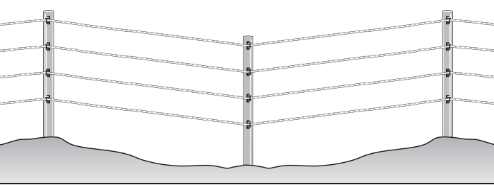
BRACING
ElectroBraid is a tension system that requires proper bracing. When the braid lines terminate at an end post or change direction at a corner post, you must ensure those post foundations are rock solid. They must be strong enough to withstand the forces transmitted if a horse were to strike the fence at speed, and resist the tendency to shift under the strain you'll provide making the line taut. For that, you'll have to ensure these posts are properly braced.
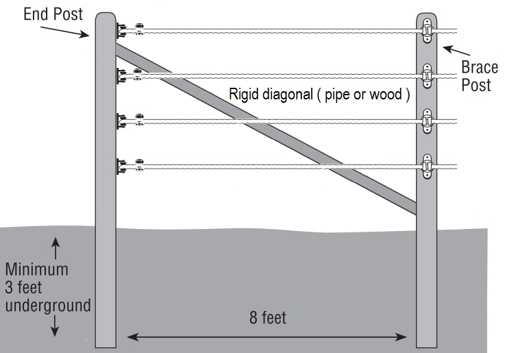
Posts should be set at a minimum of 3 feet into the soil. In areas where the ground does freeze, posts must be set to extend below the frost line. Failure to do so may cause your posts to shift, allowing the tension on the braid to relax. Consider cementing your posts or driving them deeper in loose soil conditions such as sand or mud. Please check with your county office or contractor to determine the local frost line or possible special bracing needs based on your specific soil or geographic area.
Proper bracing will increase the effectiveness of your fence and reduce maintenance caused by post shifting. Incorrect or insufficient bracing may lead to fence failure and may be dangerous to you and your horses.
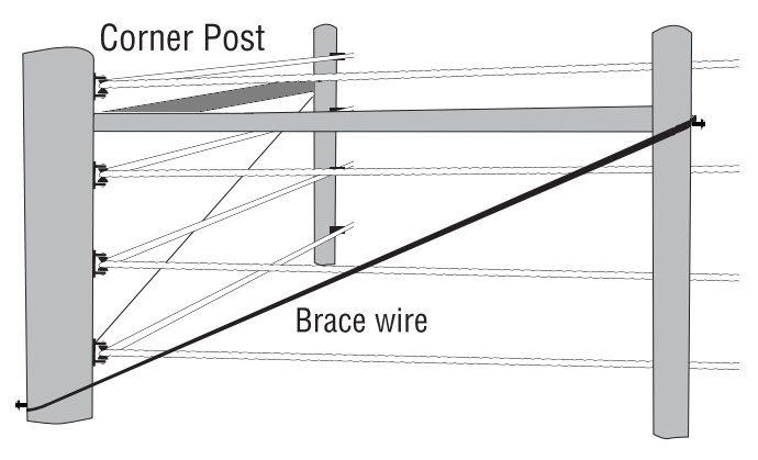
Diagonal Wood Brace
In this very common brace technique note the use of line post insulators on the diagonal. This ensures the braid is insulated from contact.
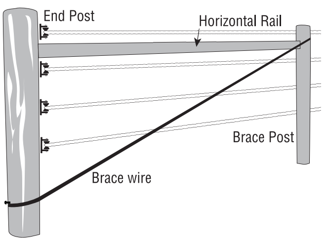
Brace with Braid or Wire
The H-Brace
The Brace with Wire or Braid system requires the Horizontal or H-Brace. After setting your corner post, end post, or gate posts in the ground at the proper depth for your soil conditions, measure 8' down the fence line to locate where to place your brace post. Once it's securely placed, set your horizontal rail halfway between the planned location of your top two strands of braid (see diagram). Drive a brace pin through the back of the posts and into the horizontal rail. Leave the spike to protrude ½" at the back of the brace post to hold the brace wire. The brace pin should go through the brace post and penetrate at least 3" -4" into the horizontal rail.
If your corner, end, or gate post is large in diameter, you should pre-drill a hole for the brace pin through the post and into the end of the rail.
You can attach your brace wire after setting your posts and horizontal rail. Use any material meant to have longevity for outdoor, high-tension use, such as hi-tensile wire or ElectroBraid. Loop it around both posts, going from the bottom of the end post to the top of the brace post. Set a nail at an appropriate location on the end post so the brace wire will not slide up and, similarly, on the brace post so the brace wire will not slide down. Pull the ends together and close the loop. With ElectroBraid , you can fasten it with the copper split bolt connectors. (See Splicing ElectroBraid ). To tighten the loop, you can use a tensioning stick that's repeatedly rotated within the loop before being fixed to the top horizontal rail.
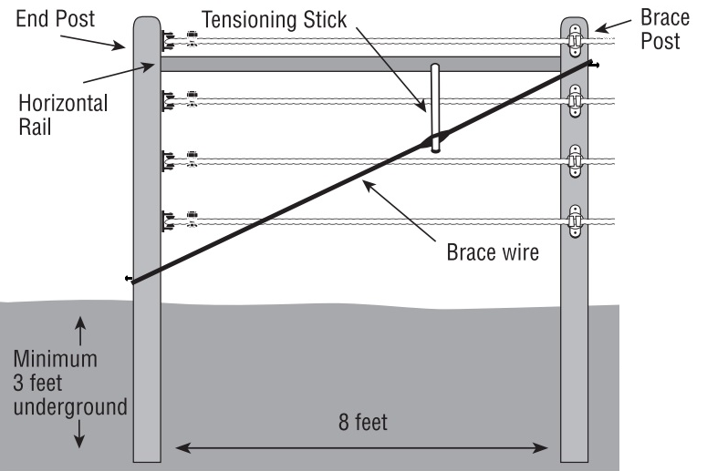
Note: To prevent an electrical short, ensure the brace wire and tensioning stick cannot contact any ElectroBraid strands.
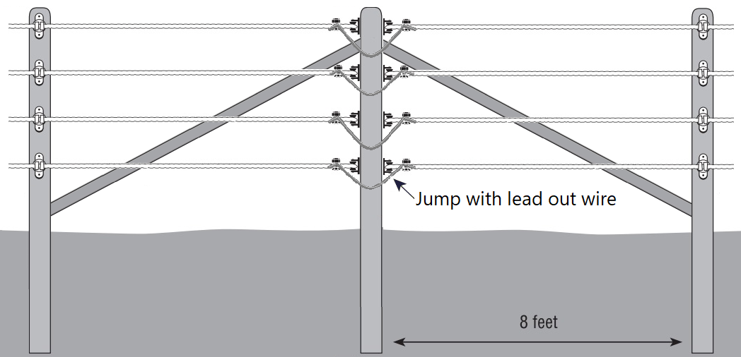
IN-LINE BRACE POSTS
There is a third category of posts necessary when building very large fences. No run of braid should be longer than 2,000 feet without an inline post bracing system. Any larger and it would be impractical to maintain the proper tension on the braid.
Ensure all braces have been completed BEFORE installing ElectroBraid.
8. Installing Insulators on Corner, End & Gate Posts
After setting and bracing all corner, end, and gate posts, you are ready to fasten insulators. Since wood conducts electricity, you must use insulators on all posts, including brace posts, to eliminate electrical shorts.
For Corner, End and Gate posts use ElectroBraid Roller Insulators. They are specially engineered:
- To eliminate friction when tensioning
- For safety
- For durability
- For ease of installation
Measure and mark the location of each of your planned strands of braid on one of your end posts and then make a jig to help you mark your other posts. (A jig is simply a stick on which you indicate the position of each insulator so you don't have to measure at every post).
Attach ElectroBraid Roller insulators by using 2 ½"
rust-resistant screws - sizes #8 or
#9. Ensure the roller pin is fully seated by tapping the pin head firmly.
Caution - BE SURE NOT TO OVER-TIGHTEN because this may bend the insulator
bracket, preventing the pin from setting properly and causing the roller to release. Complete the
installation of
insulators on your corner and end posts using the jig for spacing.
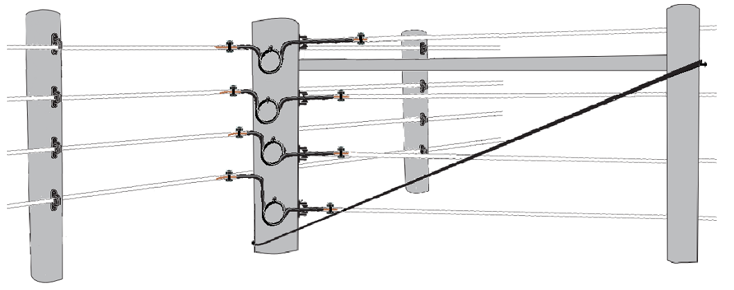
Roller Insulators on 'Inside' Corners
The preferred method is to pass the braid around the back of the post, as shown in the diagrams...
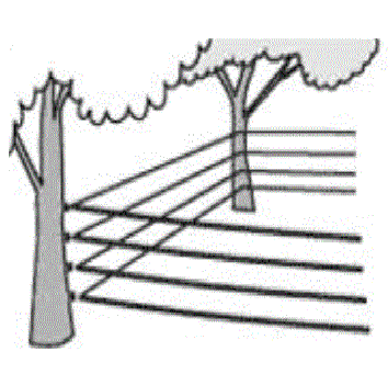
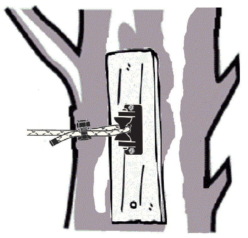
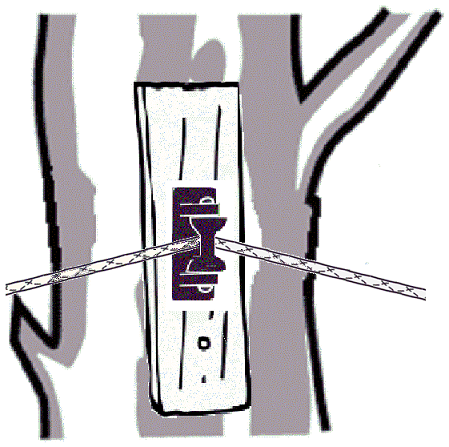
9. Using Trees For Corner, End & Line Posts
If you are running ElectroBraid through a mature wooded area, you may want to use standing trees for posts. A mature tree (8" min) can provide an excellent brace. Pre-attaching a board will prevent tree growth from 'swallowing' the insulator.
Note: Remove any brush that may come in contact with the fence.
WARNING: Avoid Small trees that can move in the breeze and wear the braid.
10. Installing Line Posts
After completing the corner and end posts, you're ready to install your line posts and their insulators.
You'll need a sight line. Starting at a gate or end post, feed the ElectroBraid® through the second roller insulator from the bottom and secure it to itself using a copper split bolt connector. The split bolt should be about 2" from the end insulator. Leave at least 2" of braid outside the copper split bolt connector. Tape, cut, and singe/melt the braid end with the lighter to prevent fraying. Pick up the reel and walk the fence line. Insert the ElectroBraid behind each corner post insulator. When you reach the end post, insert the ElectroBraid behind the end post insulator and secure it with a copper split bolt connector. Attach the tensioning device and tighten (see Tensioning ElectroBraid ). Then loosen the copper split bolt connector, pull out the slack and re-tighten. The sight line you have created will help you position your line posts in a straight line.
On hilly terrain, install line posts at the peaks and valleys first, and then space the remaining line posts to suit the terrain. Roller insulators are recommended for posts where there is a horizontal or vertical change in direction. The use of other insulators could allow the braid to pull out under tension.
Note: Always work with the "lay" of the land. Place a post at the top of each rise and the bottom of each depression. The recommended distance between line posts is 25-35 feet. Reduce post spacing in hilly terrain and areas of high snowfall.
Installing Wood Line Posts:
Install your line posts using the existing strand of ElectroBraid as a sight line. Mark the position for each insulator with your jig, and attach each line post insulator and each ElectroBraid Roller Insulator to all posts.
Note: The ElectroBraid Roller Insulator will withstand a greater force from a vertical change of direction than a conventional line post insulator. To install the braid on a line post at a peak or a valley, first tension the braid. Then, after the braid has been tensioned, remove the roller pin, place the braid behind the roller, and re-insert the pin, ensuring the pin is set all the way by tapping it with a screwdriver. The braid may jam in the insulator if you insert it behind the roller and then try to tension.
Installing T-Post Line Posts:
Layout all your posts and mark each for the depth to drive the post and the location of each insulator. Using the first strand of braid as a sight line, use a post pounder to set your T-Posts. (IMPORTANT: be sure your T-Posts are correctly oriented. The flat side of the T-Post should be on the inside of the paddock so the braid will be on the inside of the paddock when attached to the insulators.) Then attach your T-Posts insulators.
Note: A T-Post Cap provides an insulator for the top strand and reduces the hazard of a horse being speared by a T-Post.
11. Running your Line
Mount the reel on a spindle (or axle/rod/dowel) inserted through its center hole, so it can rotate freely and pay out evenly as you walk your fence line. At each line post, fasten the strand of ElectroBraid to each insulator.
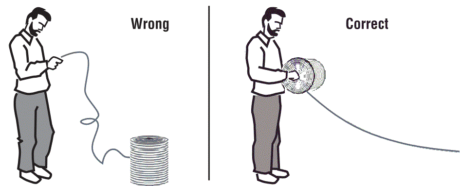
DO NOT take the braid off one end of the spool. The braid will kink and could be damaged. (See diagram)
Continue unrolling the braid until you come to an end post where the strand will terminate. End the strand by attaching it to the end post insulator just as you did when you started the strand. Pull hard on the braid to remove as much slack as possible before applying the tensioning device. Clamp the ElectroBraid to itself using a copper split bolt connector approximately 2" from the insulator.
Note: When installing a fence on rolling terrain, tension all lines first before attaching the braid to the dip and ridge posts.
Dip Post
Ridge Post
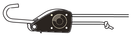
12. Tension Kit Assembly
13. Tensioning ElectroBraid
After installing a strand of braid, you can apply the ElectroBraid tensioning device.
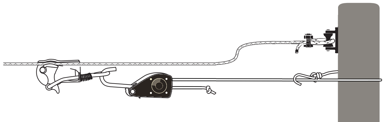
Position the clamp on the strand you are tensioning and attach the ratchet as shown.
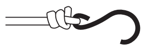
Wrap the end of the ratchet rope with the "S" Hook around the post and fasten it to the ratchet rope.
Pull as hard as you can. Do not tension the braid with a tractor, come-along or any other mechanical device. Don't worry about over-tensioning when tightening by hand. When you can't pull anymore, loosen the split bolt connector, pull out the slack you have created and re-tighten the split bolt connector. To release the ratchet, apply pressure to the ratchet rope while pressing on the ratchet's release tab and allow the rope to slide out carefully.
CAUTION: ALWAYS USE EYE PROTECTION WHEN TENSIONING.
It's possible for a copper split bolt connector to slip and/or an insulator to break. It can become a
dangerous projectile.
Wrap black electrical tape around the braid before you cut it. Using a utility knife, cut the ElectroBraid and then melt both ends with a lighter to prevent fraying.
Note: Always tape ElectroBraid before you cut it. Always singe the end until it melts so the rope won't fray when the tape wears off.
Loosen and remove the tensioning device and return to the post at the beginning of the strand. Just as you tensioned the braid where you terminated the strand, tension once again at the post where you began. Tensioning from both ends helps to ensure you get full and even tension on the line.
Note: After the initial tensioning, let the braid sit for 24 hours, then re-tension to complete the tensioning process.
ElectroBraid maintains its tension very well, so you won't have to constantly re-tension. However, if one of your posts moves due to frost or the impact of an animal or vehicle, the ElectroBraid will need re-tensioning. Re-set the post and apply the tensioning device to re-tighten the braid. Consider strengthening your bracing to ensure the post won't shift again.
If you are fencing a paddock or pasture an acre or larger, we recommend you tension from corner to corner. To do this you'll require a second tensioning kit. Starting at an end post, walk the perimeter until you come to the first corner. Tension this corner. Leave the tensioning kit in place.
Go to the next corner and repeat the process with the second kit. After tensioning, return to the first corner, remove that kit, and move to the third corner. Repeat this process until you have tensioned the entire perimeter of your fence.
Remember to terminate the ElectroBraid after every 2000 feet if in a straight line. Do this by installing an Inline Brace.
The ElectroBraid Tensioning Device does not stay on the fence. Store it until needed.
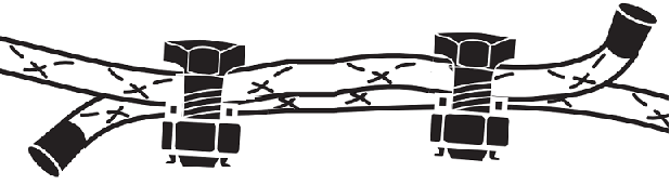
14. Splicing ElectroBraid
When you end one reel of ElectroBraid and start another, you'll have to splice the two reels together. Simply overlap the two ends of ElectroBraid by about 4" and then use two copper split bolt connectors to secure them together. Ensure there is direct contact between the copper strands in each line of braid. Make sure you tape and singe both ends of the braid.
15. Electrifying the Fence
Choosing Your Energizer
It is vital that the energizer you choose has sufficient power to meet your needs. The marketing of electric fence energizers is extremely competitive and manufacturers wildly overstate the length of fence each energizer can adequately electrify. Divide the manufacturer's mileage rating by 10 and use that value to guide your choice of energizer.
Warning: Only use a LOW-IMPEDANCE, UL or CSA approved energizer. These are a type of fence charger designed to deliver a short, powerful pulse of electricity. The pulse is strong enough to act as a deterrent but short enough to minimize harm to animals or people who come into contact with the fence. NEVER use an energizer labeled "WEED BURNER", "WEED CHOPPER", or a continuous current energizer. Their use with ElectroBraid is unsafe, and they WILL DEFINITELY damage ElectroBraid.
Warning: Never use ElectroBraid or regular house wire for your electrical connections. Only use a heavily insulated wire rated for >15,000 volts as your lead-out wire. Only use copper-clad ground rods and copper ground rod clamps.
Note: We recommend a surge protector between the power source and your energizer to protect your energizer investment.
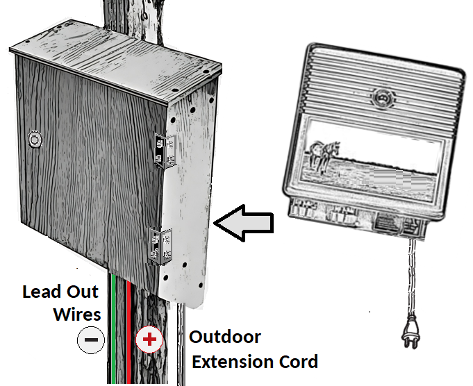
Housing your Energizer
First, decide where to locate your energizer (also known as a "fencer" or "charger"). You can use a solar-powered energizer or an AC-powered energizer. Solar-powered energizers will require careful planning and installation to ensure reliability. Your AC energizer should be shielded from the weather, out of reach of children, and away from flammable material.
One recommended solution is to place the energizer in a dedicated housing. A rough bottomless cabinet mounted on a post will allow for ventilation and weather protection. Use an exterior-grade extension cord and ensure the connection is made weatherproof and wrapped in electrical tape inside the cabinet. A "W" symbol is used on retail packaging to indicate cords made for outdoor use.
Grounding System
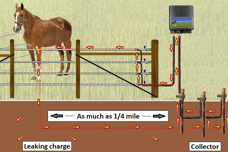
A fanciful yet useful view of an electric fence.
The energizer provides the fence with a potential charge. When a horse makes contact with ElectroBraid, the charge flows from the energizer, down the lead-out wire, along the braid, passing across to the animal's body, and through the feet to enter the soil. The ground rod installation draws much of that charge and completes the circuit by returning it to the energizer. Some of the charge will leak wastefully away into the earth. We can avoid that loss with a good ground rod system that will collect much of that charge. The more the ground rods collect, the more vigorous the circuit, the more competent the message to your horse. A good ground system can pull an effective charge in from a fence contact 1/4 mile away.
We recommend a minimum of three copper-clad ground rods, 6-8 feet long, spaced at least ten (10) feet apart in a triangular configuration. A charge passes easily through water, so look for soil that is wet or moist year-round to place your ground rods. Dry, rocky, sandy, or frozen soils will hamper the electrical return, and more ground rods may be required.
Grounding is one of the most critical elements in any electric fence system. Over 95% of all electric fence problems result from poor grounding.
The ground rod system should be near the energizer but no closer than 25 feet to help prevent lightning damage. It should be over 50 feet from any building, piping, cable or other grounding system. If it is too close to a waterline, the area may suffer signal interference in your phone, radio, or TV.
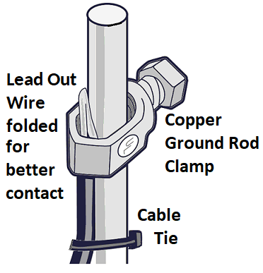
Remember to slide the clamps in place BEFORE driving ground rods. The end of a ground rod may mushroom from the pounding, making it impossible to slide a clamp over the end.
When you've installed your ground rods, connect them with the copper lead-out wire. Strip a 2" length of the insulating jacket and fold the bare wire in half. This will leave you with a chunky piece of copper to secure with the ground clamp and a cable tie for a trouble-free, permanent installation. Leave a loop of lead-out wire near each ground rod as slack for possible soil movement. After all ground rods are connected, connect one rod to the negative terminal on your energizer. Be sure the tops of the ground rods are buried below the surface of the soil to prevent the wire from getting broken or disconnected. Use small indicator flags to show where the ground rods are buried.
IMPORTANT: Check with local utility companies to locate existing underground cables, power lines or pipes before you install your fence posts and ground rods.
Siting considerations in the placement of the ground rod installation.
- No closer than 25 ft to the energizer.
- Maintain at least 50 feet from buildings, underground cables, piping, & waterlines.
- Best placed in moist ground or near water source
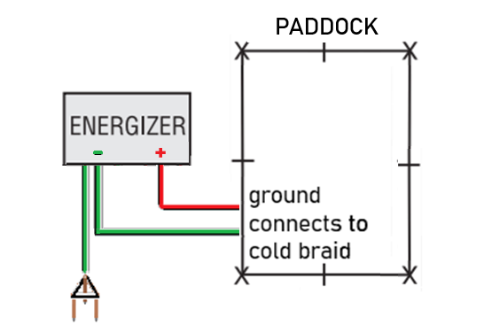
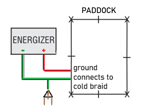
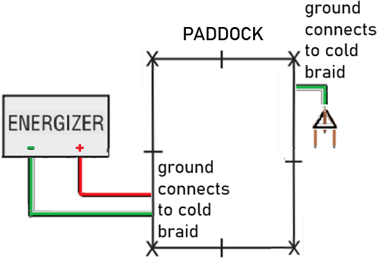
There are three patterns that can be used when determining a location for your ground rod installation. They can allow you to take advantage of favorable, low lying, moist ground. The fence's cold/ground ElectroBraid® line and the ground rod installation must be connected with the energizer's negative terminal. When convenient, they can share the same lead out wire. The ground rods can use the paddock's cold/ground braid line as part of the return path.
Solar Energizers:
Low-impedance solar energizers are perfectly suitable for use with an ElectroBraid® fence. Work with your supplier to ensure the solution provides the recommended 5,000 volts or greater, day and night, through all seasons.
Some considerations...
- Install the solar panel in a location where it will receive maximum sunlight throughout the day, ideally facing south.
- Consider possible animal contact when positioning all equipment.
- Ensure the battery is fully charged before relying on it to perform.
- Periodically check the battery voltage, especially during prolonged cloudy weather or extreme cold temperatures, and confirm consistent power to the energizer.
- Regularly inspect the solar panel to ensure it’s free from dirt, debris, frost or snow, which will reduce its efficiency.
Wiring your Fence:
Hot - Cold Wire Technique
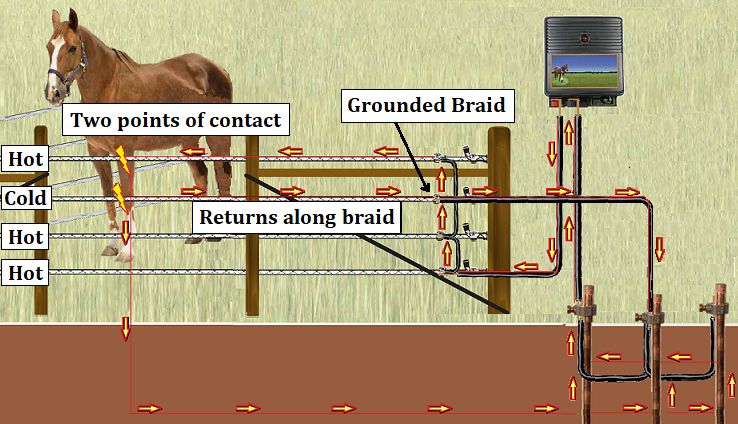
We know that a circuit must be completed for an electric fence to provide an effective shock. Rather than relying solely on the ground installation, the Hot-Cold technique devotes a strand of braid that connects directly to the energizer's negative (ground) terminal. No matter the resistance of the soil to a charge's return to the ground rod system, a negative (cold) strand on your fence will deliver a shock to any horse that touches both the negative (cold) strand and a positive (hot) strand of braid at the same time. We recommend using the second from the top strand for the negative (cold) braid line.
There is an additional advantage to this Hot-Cold technique. In the case of a fence where a distant section is well removed from your ground rod installation and maintaining a high voltage is difficult, you can install another ground rod in that area and connect it to the cold line of braid. This local ground rod can collect and return its charge down the cold line. That'll ensure that this section of the fence will provide a competent shock if the horse makes contact with only a single hot line of braid.
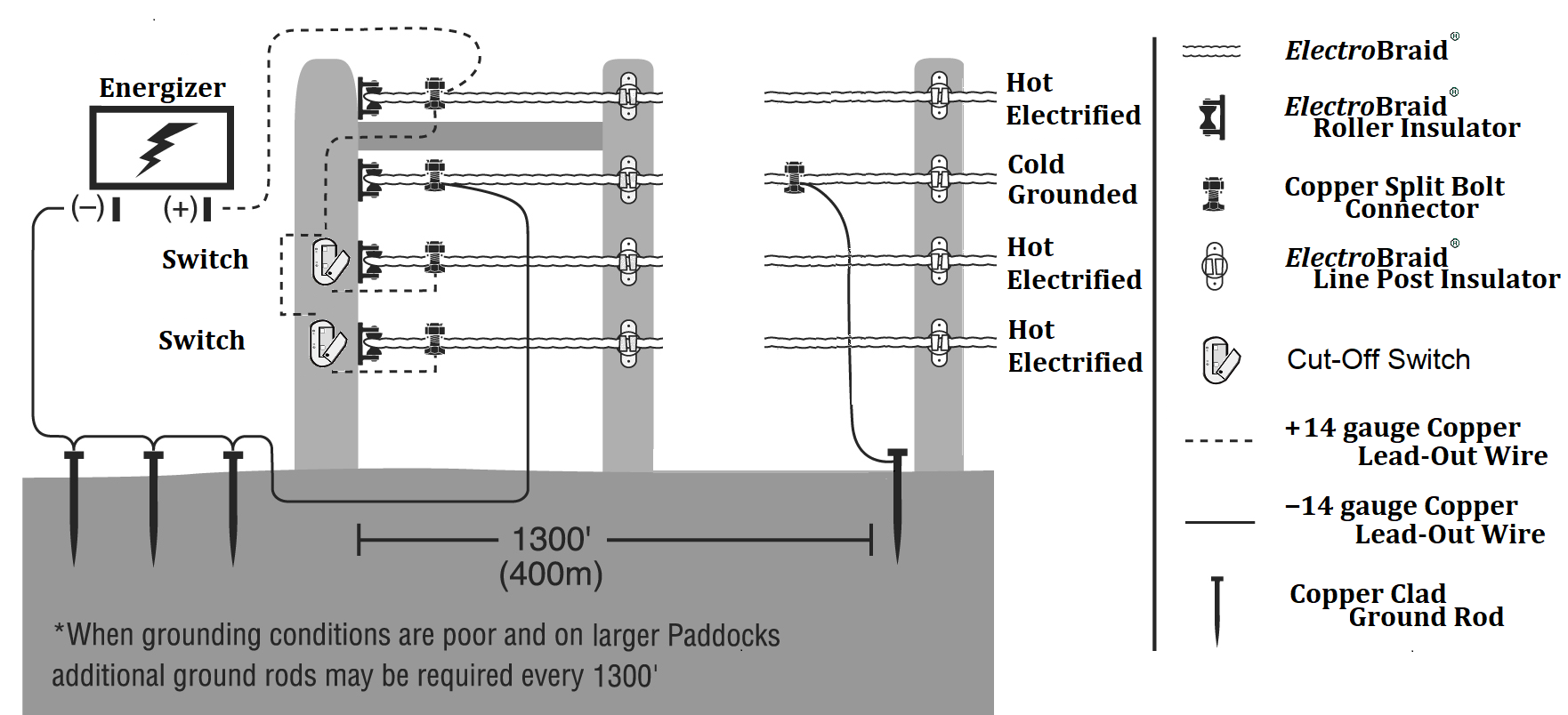
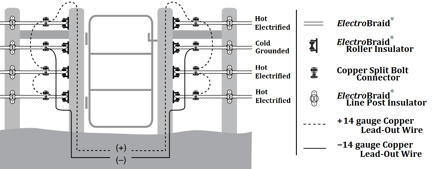
Recommended Standard Energizer Wiring
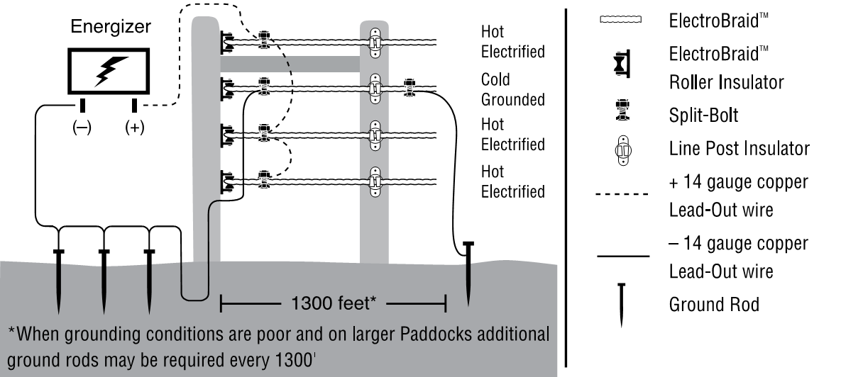
You can now connect your energizer to the ElectroBraid. Run a length of copper lead-out wire from the positive terminal on your energizer to the top strand of braid.
Note: For easier troubleshooting, it's best to use a second copper split bolt connector to attach your lead-out wire, leaving the first split bolt to maintain tension. Later, if you want to disconnect the lead-out wire from a strand, you won't need to hook up the tensioning kit.
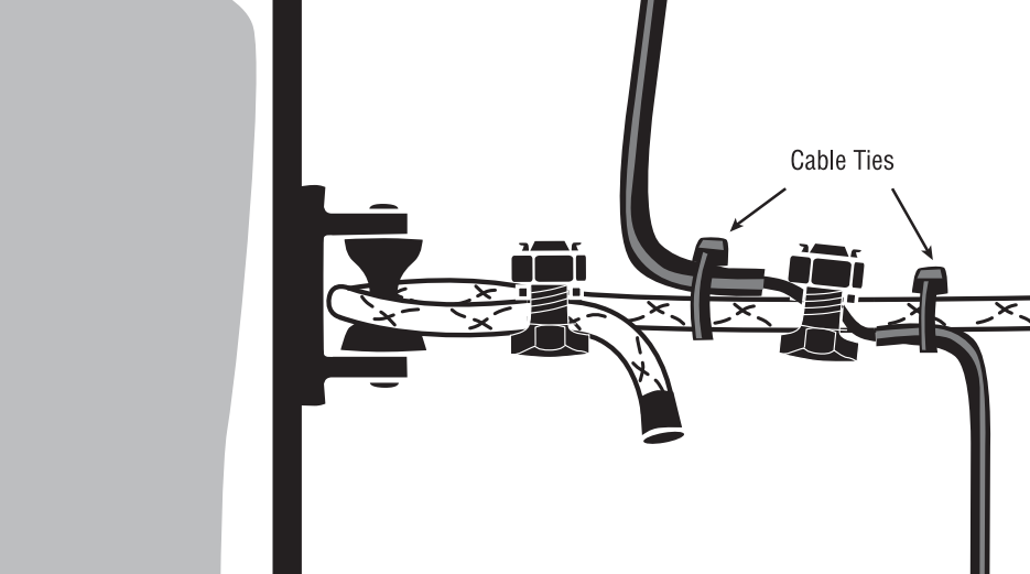
If you're using a single split bolt, attach the tension kit and relax the strand to loosen the copper split bolt. Strip away 1" of insulation on the lead-out wire to ensure a good connection and feed into the copper split bolt connector. While you have the copper split bolt connector loose, cut and insert another small length of lead-out wire to jump the electricity to the next strand. Re-tighten the copper split bolt connector, release the tension kit, and attach the cable ties. Repeat for each strand. This technique will allow you to easily disconnect the lower line(s) in case of a heavy snowfall that may cause the fence to short. Bury all wiring 8"-10" deep.
Note: If you choose to use the recommended Hot-Cold technique, then the second from the top strand will have a dedicated lead-out wire connection to the ground rod installation. The lead-out wire from the top strand will skip this strand and go straight to the third from the top, as the two above diagrams suggest.
Note: Cable ties will hold the copper lead-out wire firmly in place and help prevent damage to the connection when the strand moves or vibrates.
Note: On Underground Wiring, we recommend threading all positive wiring through a piece of ¾" conduit (flexible Poly water pipe) to avoid abrasion and prevent shorting between negative and positive wires. Bury the pipe 8" to 10" deep. Strap the ends of the pipe to the gate posts with the ends turned down to prevent rain and dirt from filling the pipe. Apply a silicone sealant to the pipe ends to help discourage housing critters.
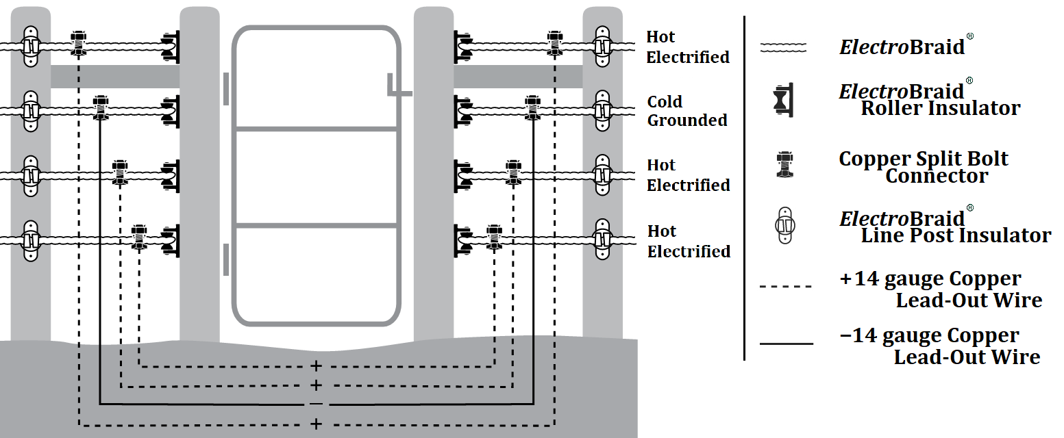
Wiring for areas of high snowfall
Heavy, wet snow can short electric fencing. To prevent this, fences in areas prone to snow accumulation can be wired, as illustrated above.
Cut-off switches can be installed to allow you to progressively turn on and off the bottom strands with the changing depth of snow. Wire your energizer as shown in the diagram.
When to wire under a gate
Wiring Gates
Dig a trench under your gate. If it's a narrow walk-through gate, then 4"-6" deep will suffice. However, if trucks or tractors will be passing through, the trench should be 8" to 10" deep.
Note: On Underground Wiring, we recommend threading all positive wiring through a piece of ¾" conduit (flexible Poly water pipe) to avoid abrasion and prevent shorting between negative and positive wires. Bury the pipe 8" to 10" deep. Strap the ends of the pipe to the gate posts with the ends turned down to prevent rain and dirt from filling the pipe. You can apply a silicone sealant to the pipe ends to help discourage housing critters.
Note: The insulation on the underground lead-out wire should not break down at less than 15,000 volts. If the guard voltage is less than 15,000 volts, the wire may leak electricity, affecting your fence's integrity. Your animals may avoid crossing the buried wire if they sense electricity beneath.
Connect a piece of lead-out wire to one of the strands by connecting the wire to the braid with a copper split bolt connector. Run the wire underground and re-attach it to the strand on the opposite side of the gate with another copper split bolt connector. To electrify additional strands, jump the electricity vertically from that strand to other strands to be electrified, as described above.
TIP –– When running underground lead-out wire, apply tape to the wire that will serve as the negative wire. Later, you'll easily identify the negative wire and avoid shorting out the system by accidentally cross-wiring the negative and positive wires.
Standard Gate Wiring Diagram:
Wiring Gates in areas of high snowfall
Note: Leave a small loop of extra wire underground to allow for the potential movement from ground heave, frost or the settling after heavy equipment movements.
Wiring a Cross-Fencing Section Or Paddock Division for Rotational Grazing
Unlike gates, there is no need to dig a trench. Simply connect the power from the perimeter fence to the section of cross-fencing using lengths of copper lead-out wire. Include a small loop of lead out wire to allow for line movement.
Using Gate Handles for Gate
If a gate will be used infrequently, Gate Handles make a very good, cost-effective solution for gaps 15 to 20 feet wide. They allow easy access to heavy equipment in or out of paddocks.
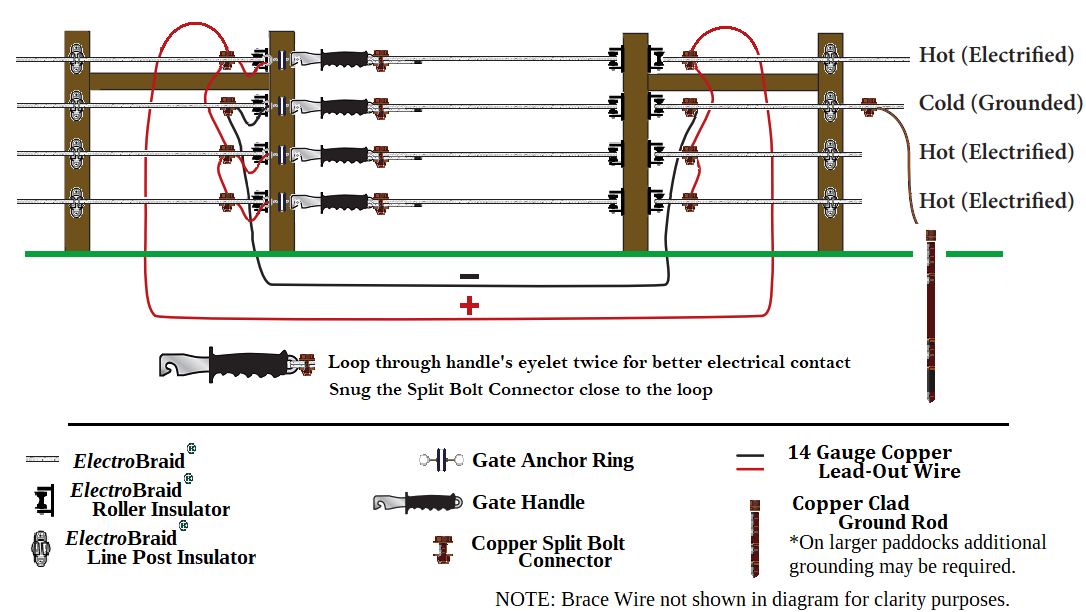
Latch Side of Gate:
- Wire the gate as described in the section "Wiring Gates".
- Install the gate anchor ring on the gate post at the same height as each strand of braid.
- Use a short length of copper lead-out wire to jump from each strand of braid to each gate handle ring.
Hinged Side of Gate:
- Install an ElectroBraid Roller Insulator on the "hinged" side of the gate post at the same height as the opposing strand.
- Attach a length of braid (about the width of the gate) to the roller insulator with a copper split bolt connector.
- Hook the Gate Handle onto the gate anchor ring. Secure the braid to the spring inside the gate handle by taking two wraps around the spring and securing it with a copper split bolt connector. It's recommended to snug up the split bolt close to the gate handle.
Note: When using trees as gate posts, mount the gate anchor ring on a 2"x4" and mount the platform to the tree. This will prevent the ring from being slowly absorbed by the eventual tree growth.
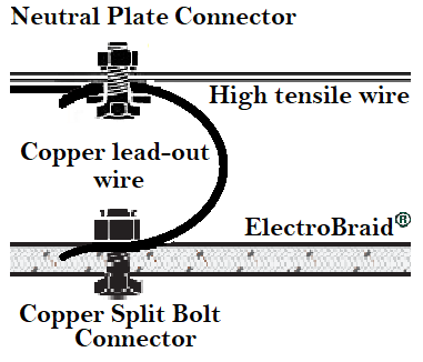
Wiring a jump from another fence-type
When connecting ElectroBraid with non-copper fencing products, you must be concerned with preventing electrolysis. This is a kind of corrosion that occurs between two dissimilar metals. A common fencing concern is between stainless steel or aluminum and copper-based products. Using a neutral plate connector will insulate the different metals from this type of corrosion.
16. Testing the Voltage on Your Fence
Testing Your Fence with a Digital Voltmeter or 5 Light Tester
- Turn your fence energizer OFF.
- Disconnect the two lead-out wires from your fence energizer.
- Turn the fence energizer ON and read the voltage on your energizer with your voltmeter. (Apply the voltmeter to the (+) terminal and the ground probe on the voltmeter to the (-) terminal of the energizer.) If less than 5,000 (5.0) volts, there is a problem with the energizer.
- If the energizer is OK, turn it OFF before reconnecting the two lead-out wires, and then turn it back ON.
-
Now read the voltage on each strand of your fence near where the energizer is connected to the
fence.
If you are using the Hot-Cold Technique:
Apply the ground probe on the voltmeter to the grounded braid line and test each electrified positive line, one after the other.If all lines are hot:
Place the ground probe on the voltmeter about one and a half inches into the soil and test the actual voltage of each positive line.You should read at least 5,000 (5.0) volts on each electrified line. If less than 5,000 (5.0) volts, there is a problem with the lead-out wire, or you have crossed wires during installation. -
Now go to the point of your fence that's most distant from your ground system.
If you are using the Hot-Cold Technique:
First, read the voltage between the grounded line of braid and each of the other electrified fence lines to confirm that the fence is wired correctly with no electrical shorts. Most importantly, check the voltage between each electrified fence line and the soil under the fence.If all lines are hot:
Place the ground probe on the voltmeter about one and a half inches into the soil and test the actual voltage of each positive line.If less than 5,000 (5.0) volts, you have a problem with your ground system. See instructions on how to Test the Earth Return System. - Finally, check the voltage to the soil at any high points or dry areas to confirm you are getting at least 5,000 (5.0) volts. If less than 5,000 (5.0) volts, you will need to install additional ground rods.
REMEMBER: ALL READINGS SHOULD BE OVER 5,000 (5.0) VOLTS
If any reading is less than 5,000 (5.0) volts, you must troubleshoot and fix the problem. These simple tests will assure you that your ElectroBraid fence is installed correctly. Please monitor your fence on a regular schedule.
TIP: Test after rain when conditions are wet to best determine if there are any electrical shorts. Shorts are more easily detected in wet conditions.
TIP: Test when conditions are very dry to confirm that you have adequate grounding. In particular, test where the fence runs over high terrain or through areas that might be especially dry or have sandy, clay or rocky soil.
Test the Earth Return System of your fence
For this test, we want to simulate contact with the fence and illustrate the fence's response to an actual touch.
- Turn the fence energizer OFF.
- Move 300 or 400 feet up the fence line from the fence energizer. Lay two or three steel stakes or lengths of pipe against the lowest hotline of the fence. DO NOT ALLOW CONTACT WITH THE GROUNDED LINE OF BRAID – it's essential that when the energizer is powered again, the electrical current flows freely from the fence lines, into the soil, and back to the ground rod installation.
- Turn the fence energizer ON.
- Move to one of your ground rods and apply the voltmeter's positive probe to its top. Hold the voltmeter's ground pin to a small steel stake (such as a large screwdriver shaft) placed in the soil as far away as possible from any ground rod. You're now measuring the difference in voltage potential of each probe. It should be small.
- The reading on the voltmeter should be 300 (0.3) volts or less. It indicates effective grounding and proper current return through the ground. The healthy flow of the current 'robs' from the voltage, dropping it to this low level.
- A high voltage reading suggests inadequate grounding. The system isn't returning a strong and competent current. The shock will be inadequate when an animal contacts the fence.
- Add additional ground rods if you're getting high voltage. Space them about 10 feet apart and at least 6 feet deep. Ensure the ground rods are connected with high-quality clamps and lead-out wire.
- Please perform this test during the dry times of the year. Dry conditions are always challenging for ground conductivity.
17. Trouble Shooting
No Respect:
If you find your horses show less respect for their fence than usual, something is likely reducing the
voltage on your fence, or the grounding of the fence is not what it should be.
Here are some things you should do:
- Follow the instructions under "Testing your Fence".
- Check all electrical connections to ensure they are secure.
- Check that the ground rod clamps are secure and the connecting lead-out wires are intact.
- Walk the fence line to ensure nothing has happened to cause the fence to short out.
- Are your horses standing on ground that is so dry or frozen that they are insulated and prevented from getting a shock? Is this a general problem, or is it localized?
- If grounding is the problem, take steps to improve grounding.
Loss of Tension:
If you detect a loss in tension, check the following:
- A post may have moved at a corner, end or gate.
- A copper split bolt connector may have slipped and needs to be tightened.
- Broken insulator
18. Dos & Don'ts – Safety and Maintenance
To keep your horses safe, use good horse sense:
- Know your horses and recognize the limitations of your property.
- Always introduce a horse to a new pasture. For your safety, turn the fence energizer OFF so the horse you lead won't get accidentally shocked and bolt. Lead the horse around the fence perimeter. Once the horse understands the boundaries of its new pasture, release the horse and turn the energizer back ON.
- Prevent your horses from accidental electric shocks by avoiding placing water troughs close to your electric fence, hanging grain pails on your fence posts, or leaving hay near your electric fence.
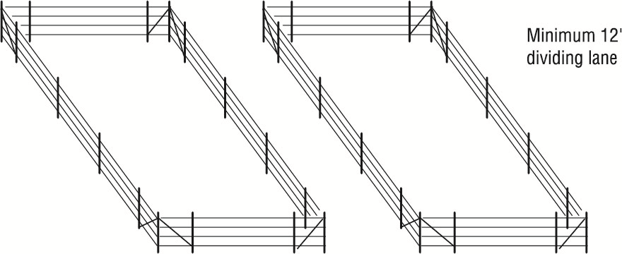
- Separate stallions from other horses by a laneway. In these cases we want the animals to maintain a respectful margin from the fence. Time spent frolicking next to the fence can allow for the possibility of wrapping a strand of ElectroBraid completely around a leg.
- Create a sandy area away from the fence for your horses to roll in.
- Take particular care when introducing a new horse to a pasture where other horses have an established pecking order.
- Don't build a new fence close to where your horses roll. If necessary, relocate the fence away from where they habitually roll.
- Do not leave your fence un-electrified as most animals will chew on it, including horses, goats, rabbits and rodents.
Fence Sense:
- Install your ElectroBraid fence as recommended. We recommend 4, or at the very least, a minimum of 3 strands of braid in normal settings. Set the highest strand at approximately withers height to your largest horse and the lowest strand accordingly based on your specific needs.
- Don't turn off your fence energizer to save electricity. The cost of electricity for a fence energizer is the same as a 100-watt light bulb.
- Regularly inspect your fence to ensure the braid is taut and properly electrified. A taut fence is a safer fence.
- Thoroughly check the fence after rainy or stormy weather and during a drought.
- Take particular care to confirm your fence is well grounded. Poor grounding is the cause of 95% of electric fence problems. Check your installation manual or our website, or call us for advice.
- Always turn the energizer off before servicing the fence.
- When testing an electric fence with a voltmeter, wear rubber gloves or rubber-soled shoes to minimize any accidental electrical shock. Wet or sweaty hands or wet feet intensify electrical shocks.
- Use only one energizer per paddock or continuous fence line. Never use two energizers on the same fence.
- Use extreme caution if you are considering installing an electric fence near overhead lines or underground power lines.
- Do not stand beside a fence during an electrical storm.
- Use warning signs to mark an electric fence every 200-250 feet. Check local by-laws.
- Never attempt to service your energizer. If it fails, seek professional assistance or send it to a certified repair center.
- ElectroBraid is engineered for your horses' safety. Don't take shortcuts.
Do not:
- Hang feed buckets on the fence;
- Drape water hoses over the fence;
- Stack feed or manure near the fence;
- Run water lines parallel to the fence;
- Allow feed or water barrels to be located too close to the fence;
- Place a water trough near the fence.
19. Hiring a Professional Fence Installer
ElectroBraid is a do-it-yourself fence system. Nine out of ten ElectroBraid customers install their fence themselves. If you want to hire a fence installer (perhaps only to install your fence posts and gates), may we suggest the following:
- Consult the ElectroBraid Installation Manual and decide the fence design you want: post spacing, bracing, number of lines of ElectroBraid , etc.
- Consult your local Yellow Pages or ask your friends for the names of two or three good, local fence installers.
- Ask for customer references and addresses where you can inspect their work.
- Get at least a couple of cost estimates.
Hiring an installer does not guarantee a proper installation. The owner's best assurance is to educate themselves so they can personally approve the final result. Please inspect your completed ElectroBraid fence and confirm it has been installed as recommended in our Installation Manual, that the post system is solid, the braid is taut, the electrical system is grounded correctly, and producing at least 5000 volts throughout the fence.
Any Questions? Call us Toll-Free at 1-855-EBFENCE. We are always pleased to help.
20. Fault Finding Chart
Relax and enjoy your new
ElectroBraid Fence!
ElectroBraid Fence!
For detailed warranty information, please visit electrobraid.com
We welcome your comments and suggestions.
Our Company Mission is to Build Safe Fences for Horses.
Our Company Mission is to Build Safe Fences for Horses.
![]()